Solved Problem on Resistors
advertisement
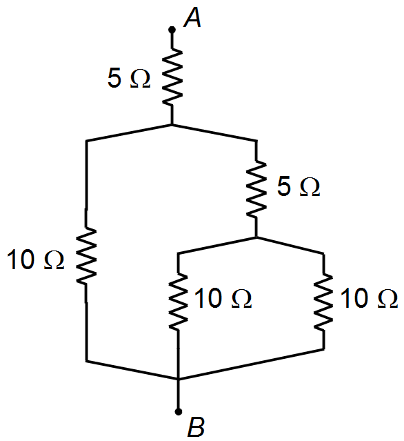
Between the terminals, A and B of the figure, it is applied a voltage of 200 V. Calculate
the magnitudes of the currents in each resistor and the equivalent resistance.
Problem Data:
- Potential difference between A and B: VAB = 220 V.
Solution
The two 10 Ω resistors, placed between points D and B, are connected in parallel
(Figure 1). The equivalent resistance for equal resistors is given by
\[ \bbox[#99CCFF,10px]
{ R_{eq}=\frac{R}{n}}
\]
For n = 2
\[
\begin{gather}
R_{1}=\frac{10}{2}\\
R_{1}=5\;\Omega \tag{I}
\end{gather}
\]
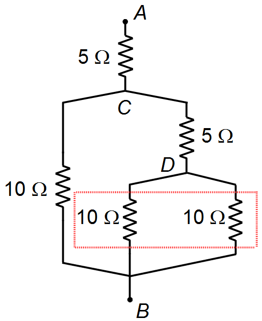
Figure 1
Note: We could also determine the equivalent resistance by applying the expression to two
resistors in parallel
\[ \bbox[#99CCFF,10px]
{R_{eq}=\frac{R_{1}R_{2}}{R_{1}+R_{2}}}
\]
\[
\begin{gather}
R_{1}=\frac{10\times 10}{10+10}\\
R_{1}=\frac{10}{20}\\
R_{1}=5\;\Omega
\end{gather}
\]
Or we could determine the equivalent resistance by applying the general expression for the equivalent
resistance in parallel
\[ \bbox[#99CCFF,10px]
{\frac{1}{R_{eq}}=\sum_{i=1}^{n}{\frac{1}{R_{i}}}}
\]
\[
\begin{gather}
\frac{1}{R_{1}}=\frac{1}{10}+\frac{1}{10}\\
\frac{1}{R_{1}}=\frac{10+10}{10\times 10}\\
\frac{1}{R_{1}}=\frac{20}{100}\\
R_{1}=\frac{100}{20}\\
R_{1}=5\;\Omega
\end{gather}
\]
The two 5 Ω resistors between points C and B are connected in series (Figure 2).
The equivalent resistance for equal resistors is given by
\[ \bbox[#99CCFF,10px]
{R_{eq}=nR}
\]
for n = 2
\[
\begin{gather}
R_{2}=2\times 5\\
R_{2}=10\;\Omega \tag{II}
\end{gather}
\]
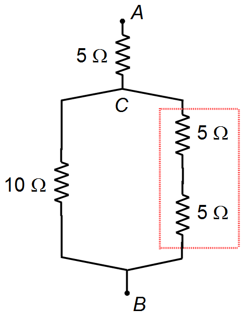
Figure 2
Note: We could also determine the equivalent resistance by applying the overall expression
for the association of resistors in series
\[ \bbox[#99CCFF,10px]
{R_{eq}=\sum_{i=1}^{n}R_{i}}
\]
\[
\begin{gather}
R_{3}=5+5\\
R_{3}=10\;\Omega
\end{gather}
\]
For the two parallel resistors between points C and B (Figure 3), we have the same result
(I) above
\[
R_{4}=5\;\Omega
\]
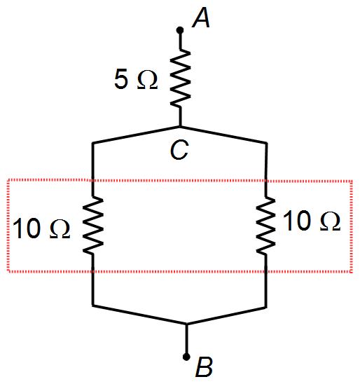
Figure 3
For the two series resistors between points A and B (Figure 4), we have the same result
(II) above, which is the equivalent resistance of the circuit
\[ \bbox[#FFCCCC,10px]
{R_{eq}=10\;\Omega}
\]
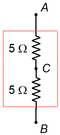
Figure 4
The Ohm's Law is given by
\[ \bbox[#99CCFF,10px]
{U=ri}
\]
substituting U = VAB = 220 V e r = Req = 10 Ω
(Figura 5)
\[
\begin{gather}
V_{AB}=R_{eq}i\\
i=\frac{V_{AB}}{R_{eq}}\\
i=\frac{200}{10}\\
i=20\;\text{A}
\end{gather}
\]
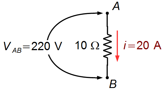
Figure 5
Returning to the circuit of Figure 4, we have two series resistors, in this case, the two resistors are
flowed by the same current (Figure 6)
\[ \bbox[#FFCCCC,10px]
{i_{1}=20\;\text{A}}
\]
\[
i_{2}=20\;\text{A}
\]
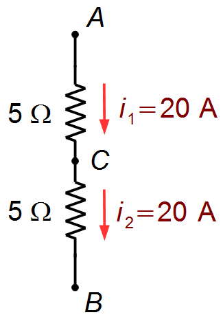
Figure 6
Returning to the circuit of Figure 3 we have two resistors of the same value connected in parallel
between points C and B, in this case, the current i2 is also divided
between the two resistors (Figure 7)
\[
\begin{gather}
i_{3}=i_{4}=\frac{i_{2}}{2}\\
i_{3}=i_{4}=\frac{20}{2}\\
i_{3}=i_{4}=10\;\text{A}
\end{gather}
\]
\[ \bbox[#FFCCCC,10px]
{i_{3}=10\;\text{A}}
\]
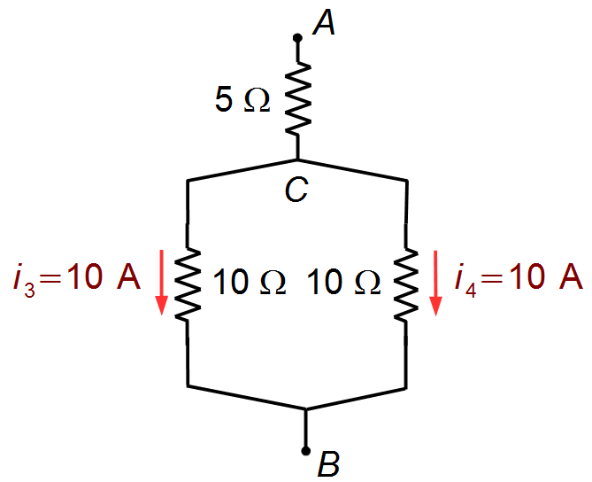
Figure 7
Returning to the circuit of Figure 2, we have two series resistors, in this case, the two resistors are
flowed by the same current (Figure 8)
\[ \bbox[#FFCCCC,10px]
{i_{5}=10\;\text{A}}
\]
\[
i_{6}=10\;\text{A}
\]
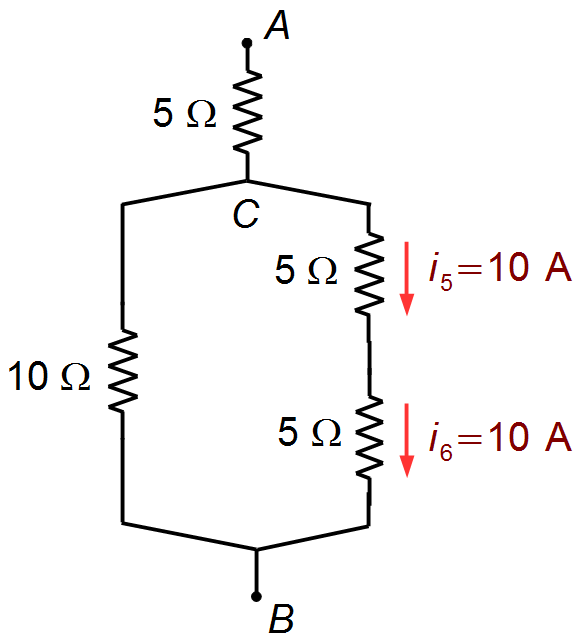
Figure 8
Returning to the circuit of Figure 1, we have two resistors of the same value connected in parallel
between points D and B, in this case, the current i6 is also divided
between the two resistors (Figure 9)
\[
\begin{gather}
i_{7}=i_{8}=\frac{i_{6}}{2}\\
i_{7}=i_{8}=\frac{10}{2}
\end{gather}
\]
\[ \bbox[#FFCCCC,10px]
{i_{7}=i_{8}=5\;\text{A}}
\]
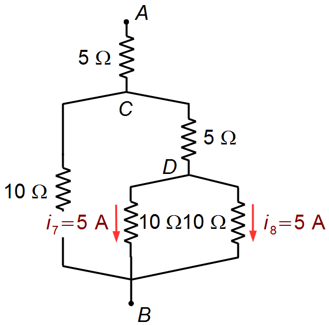
Figure 9
The complete diagram for the currents will be (Figure 10)
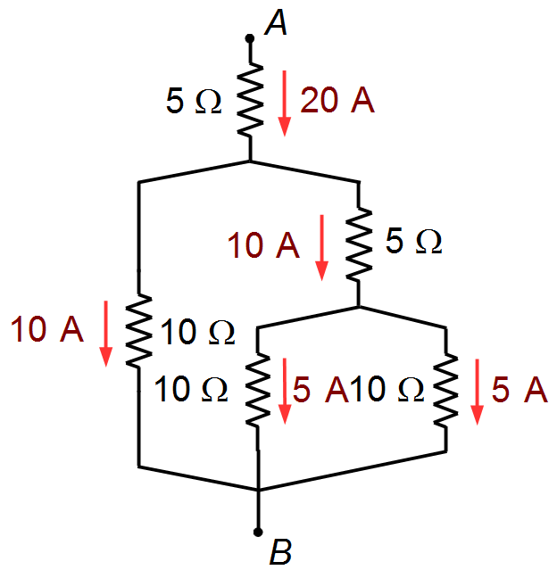
Figure 10
advertisement

Fisicaexe - Physics Solved Problems by Elcio Brandani Mondadori is licensed under a Creative Commons Attribution-NonCommercial-ShareAlike 4.0 International License .